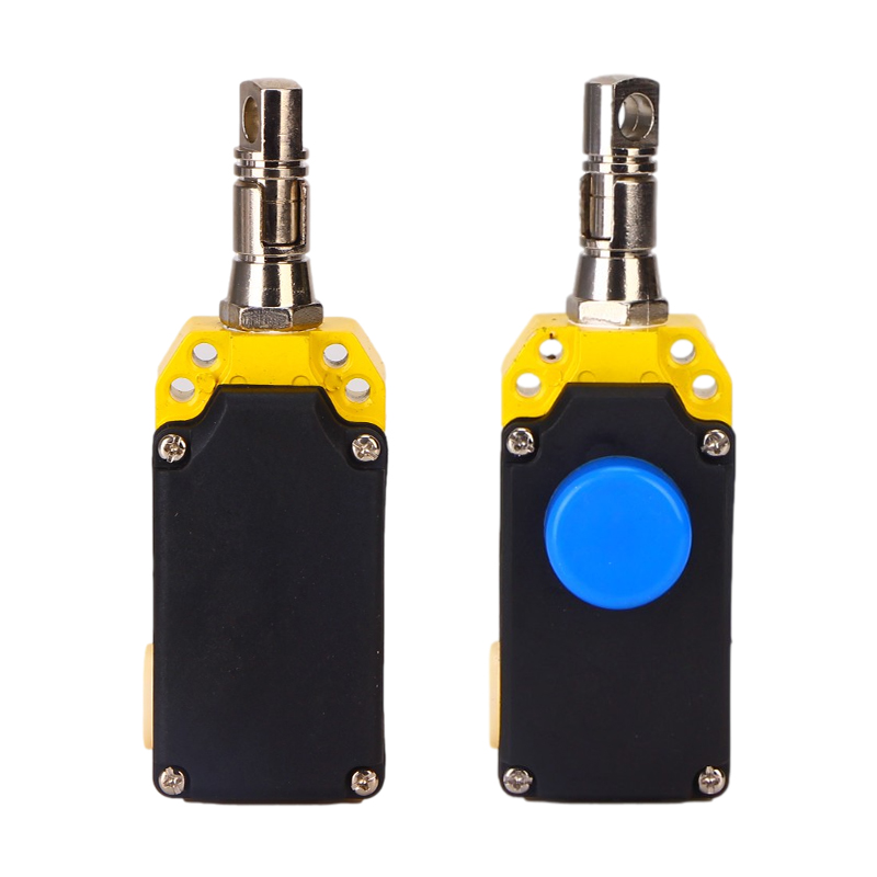
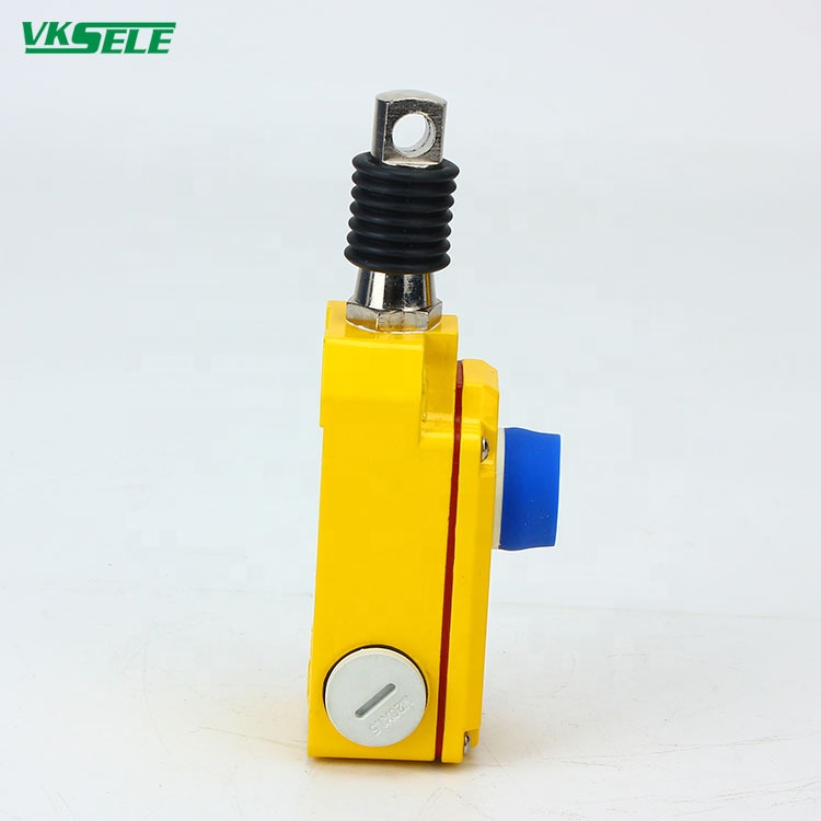
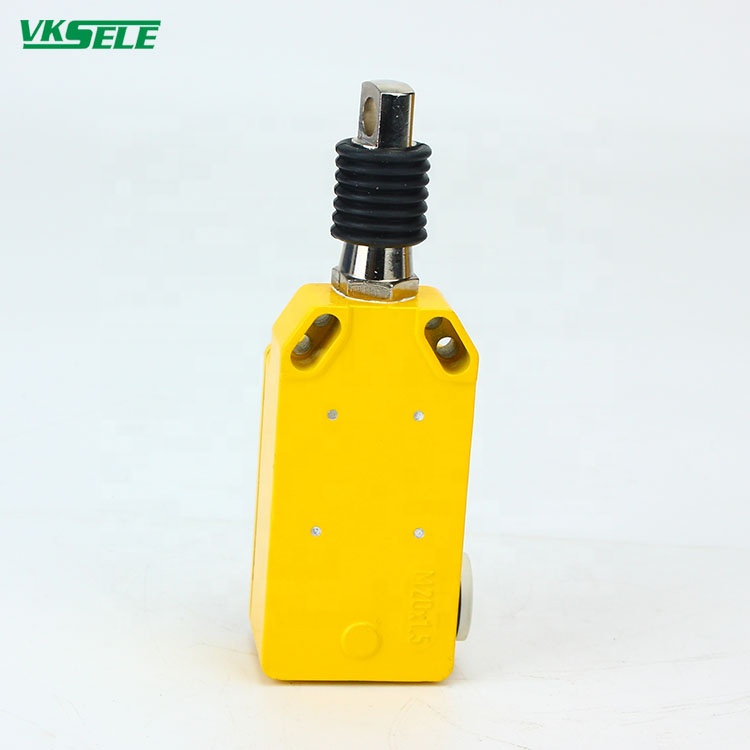
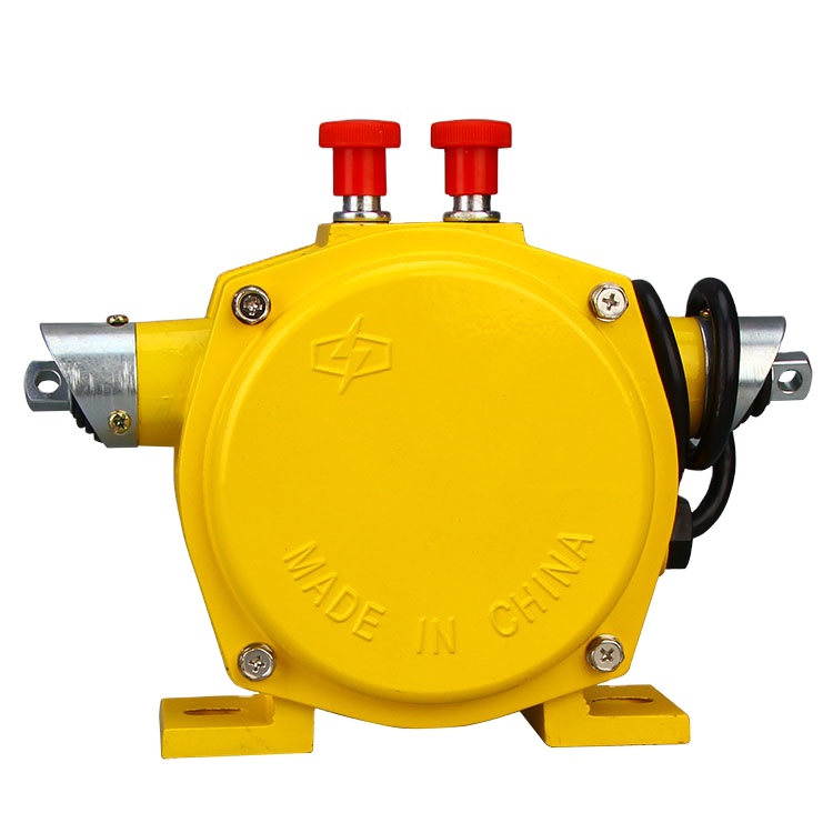
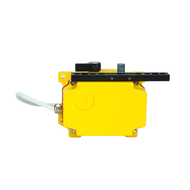
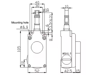
Pull Wire Switch
Working principle:
The pull wire switch is fixed according to the installation instructions. When the switch is pretensioned, contacts 11-12 and 21-22 are turnedon. When the pull wire is pulled or disconnected, the contacts are forced apart while the state is locked, and unlocking can be achieved with a button or key.
Technical indicators :
Rated Voltage | Non-Inductive Load | Inductive Load | ||||||
| Resistive Load | Lamp Load | Inductive Load | Motor Load | |||||
| NC | NO | NC | NO | NC | NO | NC | NO | |
125V AC 250V AC 480V AC 600V AC | 10 5 3 1 | 10 5 3 1 | 3 2 1.5 1 | 1.5 1 0.8 0.5 | 10 5 3 1.5 | 5 3 1.5 1 | 2 1 0.8 0.5 | |
8V DC 14V DC 30V DC 125V DC 250V DC | 10 10 6 0.8 0.4 | 6 6 4 0.2 0.1 | 3 3 3 0.2 0.1 | 10 10 6 0.8 0.4 | 6 6 4 0.2 0.1 | |||
Note:
Inductive load power factor=0.4 ( AC ) , time constant=7msec
The inrush current of the lamp load is 10 times of the steady
The inrush current of motor load is 6 times of the steady
- ← Previous:Square Ramsey Pull Cord switch
- Explosion-proof Pull Cord Switch :Next →

 Zhejiang Weikesen Power Technology Co.,Ltd.


